
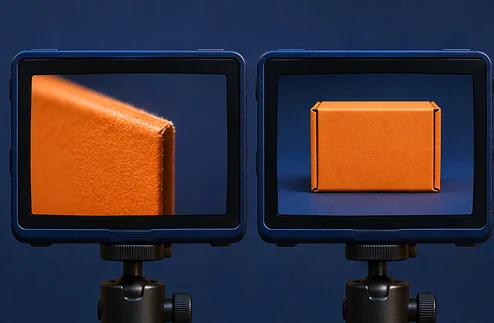
Choose a camera view by identifying the smallest feature the reviewer must see, testing the view under ordinary positioning changes, and comparing it with plausible alternatives. A wide, sharp picture can still be a poor inspection view if the feature is hidden by the part itself.
Sketch the feature in relation to the product
For a carton label-position check, the useful image includes both the label edge and the edge or corner used as the position reference. For an insert check, it includes the expected slot and enough surrounding shape to know which slot is shown. Start by drawing the feature and the adjacent landmarks on a paper copy of the proposed view. Mark the parts an operator can physically obscure with the fixture or handling steps.
The reference location should be preserved when the product is rotated or translated within allowed bounds. A frame edge is convenient to point to, but it moves relative to a part that slides in a tray. If the fixture establishes a consistent position, agree on how the setup will show when the part is seated. Where the part moves, test whether the product’s own geometry remains usable as a landmark.
Compare the alternatives using the same units
Image one small set of representative physical units from each proposed view. Include a pass, a clear defect, and an ordinary ambiguity. Keep scene variables as consistent as possible during this comparison. If one view makes the rough wrinkles in a carton look like a shifted label, inspect the paired image and the physical sample before declaring which view is stronger.
| Candidate view | Evidence available | Known limitation |
|---|---|---|
| Head-on front face | Both horizontal label edges and the carton frame | Specular highlight can cover one edge |
| High oblique | Top flap, front edge, and label upper edge | Perspective makes lower-edge comparison harder |
| Side | Carton seam and front-to-side relationship | Little direct evidence of label alignment |
Ask independent reviewers to mark the decisive edge or part in each image. If they cannot point to an agreed feature, save their disagreement as evidence. A view should be judged by what it makes obvious for the particular question. Color fidelity, focus, and coverage can all matter, but a general image-quality score does not replace inspecting the actual feature.
Allow room for the way the line operates
Capture after a changeover and after an operator loads the part normally. A view that works only when an expert adjusts the carton carefully may be hard to repeat. Assess horizontal shift, rotation, motion, ordinary height changes, and whether a hand, guide rail, or next unit obscures the view. Give each case a condition label so the team can check it against later trial results.
When considering an extra view, define what it recovers and how its record is tied to the first view. A second front image with nearly the same glare may add little. A second angle that removes glare can help if the pair is easy to associate and the timing fits the handling process. It creates another capture condition to evaluate, and the procedure must say what to do when one image fails.
A vendor-specific example of capture and part positioning is Cognex’s image acquisition and part placement documentation. Use it as a terminology reference and scope your own view against your actual fixture, product, and station.
Record the selected setup and its boundary
Write the approved view as a reproducible instruction. Include the station, feature, camera position, the reference used to align the part, and at least one photograph of an acceptable setup. Put one unusable case next to the acceptance reference to show the limit. Name a reviewer who can resolve photos outside that scope and describe how the team can capture another view safely.
If a material or fixture changes, retake a known sample using the same reference. Compare which parts remain visible. Resolve any loss of evidence before using the new view for evaluation. The view selection worksheet stores the relevant observations, and the lighting guide helps separate geometry problems from visibility problems.
Convert the customer requirement into a view drawing
Draw only the faces the inspection can observe. For a label position check on a square carton, sketch the face on which the label sits and mark the physical edge from which its offset is specified. Put a second mark on the edge of the label that determines the result. When you can point to both marks in an unedited image, a reviewer has the elements to interpret the position. If the drawing instead measures an offset from a flap that bends with closure, your view study also needs to establish whether the datum is available and stable at the chosen station.
Identify each thing you expect the camera to see as an item on the drawing. Record the target, reference, allowable surface, possible obstruction, and orientation. Some requirements involve a single near-planar face. Others involve a surface wrapping around a corner, an underside clip, or an opening whose depth needs another view or a different sensing method. A lens sees along its line of sight. If the requirement covers a feature behind another part, consider a different point in the process before trying a wider lens. Test the drawing against several actual units and a range of ordinary positions.
Ask the operator to point to the exact viewing moment. A feature can be visible as a carton enters a station, disappear behind a guide during capture, and reappear before the next handling step. A drawing made while the line is stopped may omit the guide bracket or the hand that stabilizes the product. Visit or represent the real position, orientation, and motion at capture. Record which steps you expect the operator to do and how long the product is available for observation. That stops a workable bench view from becoming an awkward live procedure.
Agree on whether evidence can be split across views. A carton check might use one clear frontal image to assess placement and an overhead image to confirm both flaps are present. Keep them as separate decisions for the same unit. Their views can have different capture dates, quality rules, and uncertainty reasons. A test that only provides one passing verdict for “carton inspected” gives the next person little information about a missing reference.
Compare field of view and detail on the same feature
Start with the objects that need to fit in the frame. Reserve room for ordinary changes in position and orientation. If a fixture allows a 5 mm offset on either side, account for both limits. With a wider field of view, you will generally get less image detail per physical unit on the same sensor. Measure the result on the target feature rather than relying on a manufacturer’s sensor pixel count alone.
Here is a fictional starting estimate. A flat field of view spans 240 mm across an image with 1,920 active pixels. At a plane where the mapping is approximately uniform, that is eight pixels per millimeter. A 1.5 mm feature would span about twelve pixels across that dimension. If the view widens to 320 mm on the same sensor, the estimate becomes six pixels per millimeter and nine pixels across. These are arithmetic estimates for a specific plane. They cannot guarantee the feature has enough contrast, stays in focus, or remains visible when a product rotates. Derive the real comparison from paired images of known specimens under expected conditions.
Save pictures at their actual analysis scale. The image a person sees in a browser might be displayed at half resolution or stretched to fill a viewport. A preview can make an edge look sharper or softer than the crop passed to the check. Record whether the measurement comes from raw pixels, a reduced copy, a rectified crop, or a visible overlay. Reuse the same transformation when comparing the candidate views. Where one camera view requires more cropping, make sure the remaining features still carry the needed detail.
Select a more useful view before shopping for resolution. A higher-resolution camera looking at the blocked side of a carton can produce a clearer image of the obstruction. A modest camera pointed at a later station where the edge is exposed may reveal it. Compare the trade on several known units. Include the smallest target, the least contrasted material, and the maximum routine displacement. Note the age and identity of the reference measurement so the new view can be judged on the same condition.
Decide whether perspective must be corrected
Use a repeatable mount and reference if you need to compare positions in physical units. A straight-on view of a planar label can make the measurement easier to interpret. An oblique view can help see a depth feature or avoid a strong reflection. Its projected distances and apparent angles can vary with where a package sits. A shifted result may indicate camera or product pose rather than label movement.
Compare a simple front-facing setup and an oblique setup using the same labeled unit. First place the carton against its known reference. Record the apparent offset and which edges are visible. Reposition the carton to each allowed extreme without altering the sticker. If the measured offset changes only because the item moved, the view or measurement method needs work before a pilot can measure placement. If the amount of movement is within your judgment uncertainty, confirm that it does not change how boundary examples are routed.
A calibrated mapping of a plane can help normalize perspective for that plane. Use observable references, known dimensions, and a documented calibration procedure. Test it after refocusing or moving the mount. An image mapped to a carton face can support x and y measurements on that face. A raised flap, concave surface, or bent label may not follow the same mapping. Put examples of these surfaces into the audit to find where the correction fails. Use a separate rule for unusual geometry if the team will keep such units in scope.
A fixture can sometimes provide the consistency at lower complexity. If products enter square and stop within a small tolerance, a fixed image region can make the check repeatable with fewer adjustments. Ask how often the fixture is changed, who restores it, and whether it damages or obstructs any included formats. Compare the time spent adjusting it with the time spent maintaining a geometric correction. Choose the practical burden the line can handle and record the accepted configuration.
Check depth and focus across the operating envelope
Measure whether the relevant surfaces are sharp at the distances they can really occupy. A reference carton held still at the center of the station does not reveal the near and far limits of useful focus. An open kit may place the insert on the bottom of a box while its flap extends toward the lens. Focus set for that flap can leave the insert soft. Focus set for the insert can make the flap less clear. Decide which surface actually determines the check, then test how far ordinary variation pushes it from the best focus.
A wider depth range can trade against lighting and exposure. Changing the aperture changes the light reaching the sensor. A longer exposure can make a moving part smear, even if a stationary sample looks sharp. Use the actual motion condition in the comparison. Where the images come from a line moving at steady speed, pick a mark that makes blur visible and test the planned exposure under an approved light setting. Keep the lamp position, product, and lens fixed so the test isolates that variable.
For example, consider a fictional fastener presence check on two bracket heights. The smaller bracket puts its screw head 30 mm lower than the taller one. Mount A shows the correct face on both brackets, but its settings make the recessed head unreadable on the smaller bracket. Mount B uses a shallower view and a fixed guide to control the distance, but the guide hides the head if the bracket tilts toward it. Use real photos of both heights under expected movement. An extra fixture change on every product switch may be acceptable for a low-volume bench and too burdensome for a fast line. Write the operator cost into the comparison.
Keep a few borderline focus images available as references. A plainly blurred frame is easy to reject. A frame with crisp lettering and soft fastener edges can surprise a person who judges overall image quality. Include known fasteners at the deepest allowable position and accepted edges near the smallest detectable displacement. Ask a reviewer to mark which pixels they relied on. If their evidence points outside the target region or they disagree about visibility, adjust the rules or view.
Test the view at speed before recording a winner
When the product moves, judge the image at the capture speed the line actually uses. A camera angle can look good while a unit is paused and produce a blurred picture at ordinary speed. Motion within the exposure depends on the time the sensor collects light and apparent movement across the image. To bound the risk, observe moving accepted and known failing units. Preserve settings and light geometry so you see how the view behaves on the station.
Write down what triggers capture. An encoder, sensor, machine event, or operator action defines when a frame arrives. If a hardware cue is used, verify the unit’s location when the frame arrives. A fixture that holds the product for long enough can simplify timing. A capture triggered by a case entering a sensor can show part of the previous case if the delay, spacing, or cue is wrong. Pair images with a unit ID and compare the sequence across a short consecutive run.
Imagine a fictional case where a front camera misses the upper edge of every seventh tall carton. A still image of the first carton is fully visible. A sequence shows that some cartons bounce slightly against the guide after an uneven handoff. The failure follows the position at capture. A second front camera mounted higher may increase margin. A delayed capture might allow settling but reduce time before the carton leaves the station. Test both options on paired groups, include small cartons to ensure the change does not hurt their view, and record the available delay.
Follow a few cartons through image and operator disposition. A camera can resolve a tiny notch that a reviewer cannot locate on a live device display. Test the display crop, magnification, and whether the marked location points to the actual image region. Record how quickly the assigned reviewer can confirm the decision. A useful view helps the entire inspection process, including the person who has to see the evidence in an uncertain case.
Test normal handling and service operations
Check safety and physical access with the responsible site team before finalizing an installation. A mount can occupy a spot the operator needs for a material change or equipment cleaning. A cable route can interfere with a guard, and regular vibration can move an unlocked bracket. The pilot drawing should identify the camera, sight line, fixture, and known obstructions. Use the site’s approved access procedure for practical tests and measurements.
Inspect where glare and dust are likely to occur. A protective window or cover can change the optical path, especially if it picks up marks. Capture a reference before and after normal cleaning using the same unit position. If the image suddenly has lower contrast or a repeated region becomes unreadable, ask what changed in the lighting or surface. Maintain a record of the approved setup so routine service can return it to the state the pilot evaluated.
Record the slots used by finishes and formats. A low carton and a tall carton can need different views at the same physical station. If you permit two recipes, give each an unambiguous selector and an observable verification step. Introduce a test where the wrong recipe is deliberately chosen using a safe test procedure. Confirm that the mismatch is visible and has a planned action. An unhandled wrong-recipe case can silently produce an acceptable-looking image with no evidence of the intended feature.
Keep an explicit procedure for a changed bracket or image crop. A tiny mount movement can shift the reference only on a few formats. Make the station baseline reproducible with a stored reference unit, an expected image region, and an accepted range of positions or appearance. Have a second person restore the setup after a routine intervention and photograph the reference. Compare original and restored frames before extending the pilot to a new station. For a comparison of exposure and highlights, see the lighting guide.
Decide what a second camera earns
Start with the evidence missing from the first view. If the first camera reliably shows the front label, a second source should add a needed fact such as the presence of a concealed flap from above. Document whether the views cover different requirements, provide alternatives for one feature, or both need to agree. Decide how to proceed when one picture is missing. Keep the defined exception if the required feature remains hidden.
Evaluate second-camera alternatives separately. Reorienting the package at an existing stop may bring a face into view. A small lighting adjustment may recover a region hidden by a highlight. A mirror can provide another angle in a single image with its own calibration and access needs. A second camera can provide the independent perspective without moving the unit, at the cost of matching captures and maintaining two setups. Test the choices on a small set of target and accepted cases. Estimate setup work, maintenance, and review time as distinct items.
Protect against cross-unit pairing. If a top camera and side camera capture along separate positions, decide how the image records will know they belong to the same unit. A timestamp alone may be ambiguous during an interruption, a skipped frame or a gap in product spacing. Use the identity your line can maintain and test that identity when a frame is absent. An ambiguous pairing should reach a person with the reason visible or recapture if the unit is still available. A complete pair from different cartons can give an especially persuasive wrong answer.
Set a rule for common imagery changes. Suppose glare makes two glossy carton edges unreadable in a frontal image but an oblique view shows the complete label and datum. That oblique view can be the assigned fallback if you have validated how to measure placement from it. If it only shows a different side, it cannot support placement regardless of its clarity. Keep the route that recovers evidence at the bench. Use the camera view selection sheet to compare which condition each view resolves and who makes the subsequent decision.
Run a paired comparison and retain the evidence
Use a few named study groups and a frozen candidate description so results can be reproduced. For a fictional tray manufacturer, candidate A is a view from directly above the open tray and candidate B is a thirty-degree view that shows whether a low tab engages. Prepare twelve representative units with flat and tilted trays, both tab states, and two approved finishes. Record the actual physical disposition separately. Capture each unit under both candidates using the agreed exposure and lights. Record relevant changes and which frame belongs to each candidate.
Count image usability by view and unit before measuring prediction performance. Suppose the overhead view clearly shows the location of twelve tray pockets, but the tab is hidden on four. The angled view shows the tab on eleven, but one tray wall blocks the base needed for a measurement. Show those counts separately and open the corresponding images. If a single view is required for both conditions, these results support a focused change to framing or position. If the checks can be separate, the data support evaluating a combined workflow with a rule for each view.
Try the chosen approach with an untouched group of units from a later run. Deciding on A or B using the first group makes that group development evidence. A new group tests whether the relevant features remain visible under the chosen conditions. Include cases near the edges of the approved pose and both acceptable and failing outcomes. Capture them at the planned operating pace. Have a person who knows the physical requirement verify the recorded dispositions without relying on the predicted result.
Use a reporting structure that leads to a decision. Include the view drawing, setup values, covered conditions, the comparison cases, and which known features remained unobservable. Give overall counts and a reason for each excluded case. If the project cannot test the tall carton until next week, treat that format as awaiting scope. Describe the interim method approved for those cartons. Sign off on what the evidence covers so a good result on the common unit does not imply that every possible placement works.
Use a one-page operating reference
Carry the results into a reference an operator can read at the station. Put the current camera image first. Add the expected carton orientation, the approved field of view, the visible reference, and a small number of allowed variations. Give one example of a usable boundary case and one example that needs another view. A person should be able to use that reference even when the evaluation specialist is unavailable.
Include the setup identity. Record the bracket or fixture, acquisition mode, lens or image setting aliases, light geometry and validation date. Reference the configuration record where actual settings are kept. An unversioned picture printed on a wall can survive several camera changes. Make the applicable image and product format clear when replacing it. Carry forward prior records for investigations, while keeping the current setup easy to recognize.
Test this reference with a short walk-through. Give a second operator the station, two known examples, and an expected outcome on each. Ask them to find the camera view, determine whether the required points are visible, and route a case where a guide blocks the edge. Observe whether they can find the correct file and physical item. If the action requires a person who is absent on a later shift, name the coverage or fallback before using the check. The record is usable when the responsible team can repeat the capture and assess what it establishes.
Treat a changed visual requirement as a new view question. A camera chosen to see front label location may not show the area needed to judge a tucked flap. Revisit the drawing, select comparison cases, and test the new requirement with its own measured evidence. Preserving this distinction can save a successful pilot from accumulating unrelated demands on one image. Move to pilot evaluation once the view, unknown path, and tested envelope are written down.
Work out whether the extra detail changes decisions
Set up the view test to answer a practical question. An inexpensive second view adds work if it only produces clearer pictures of units your team already classifies. A different vantage point can earn its place if reviewers use it to resolve a significant class of cases, or if a rule can reliably observe a protected feature the first camera misses. Compare the proportion of units you can decide, the time to settle the others, and the number of incorrect decisions under each configuration. Keep outcomes at unit level.
Suppose a fictional carton sample contains 120 independent units. Under the front-only setup the required reference is clear on 106. Ten of the remaining 14 cases show a strong light band over the label edge, and four are rotated far enough that the front face leaves the approved view. The side view recovers some information for all four rotated cases, but none of those side images contains both edges needed for the front placement measurement. If the rotated cases are important, investigate why the carton can rotate at the station. Adding a side measurement that cannot answer the placement question creates more images to inspect while leaving the decision unchanged.
Now consider the glare cases. Replaying the same camera positions with an approved lamp adjustment exposes the edge on nine of the ten. The tenth still needs physical review. This result gives the team a specific option. Compare how the new light affects other colors and finishes and test with a new production group. If old matte labels lose contrast, you may need a separate preset or manual routing for gloss. Preserve the earlier settings and reference frames in the decision record. The paired comparison explains why the optical change deserves validation, and the independent sample evaluates how well it generalizes.
Put numbers around the human cost where you have evidence. If an additional view takes 18 seconds to open, align and interpret, 30 uses of that view add nine person-minutes in the measured work period. A local one-time test of 30 decisions can tell you what consumes time. To estimate production coverage, track how often the second view will really be requested and how those requests cluster at changeovers. If the view is always required, include the time it takes to acquire, link, and recover missed pairs. Test the export log or review interface when a frame arrives late.
The decision about the second view can change over time. A manual station with ample space may accept a recapture procedure for a rare condition. A busy station that cannot retain product can require an earlier view or a different policy for that output. Record the assumptions with the inspection version so a change in collection timing or product mix prompts the right reevaluation.
Compare measurements when the drawing, camera and display disagree
A technical view review can turn into three separate arguments about the same feature. The drawing owner talks about physical position, the camera specialist sees a location in an image, and the operator reacts to a drawn box on a display. Resolve the mapping between these observations while somebody can hold the reference unit. If the product requirement uses the carton base and the displayed box is anchored to the image crop, show what happens when a correctly placed carton shifts inside the fixture. Determine whether the display is representing the same rule.
Test a few known cases with the full presentation. Include an acceptable unit, a unit physically measured near the limit, and a unit with evidence missing. Open the image with and without the overlays. Ask which edge generated a reading, whether the source is the camera or a stored inspection profile, and whether the marks on the display help a reviewer direct an action. Use units consistently, and measure both pixel and physical distances where practical. If the station profile stores a fixed pixel offset, document the measurement plane and the conditions that make the current mapping valid.
Where display and check disagree, preserve the raw results as well as the marks the operator saw. The form of the disagreement can isolate a defect in the presentation even if the underlying check is correct. A crop may move the annotation relative to a displayed image, an inverted view can reverse the direction of a recorded offset, or a viewer can show an earlier frame as the station advances. A clear, fresh unit identifier and version indicator can help the operator identify those issues. Validate on a successful case and deliberately unavailable evidence within a supervised test.
For your next station review, bring the original image, current display, approved drawing, and physical measurement for two difficult units. Ask the person who will approve the view to make a decision using those four pieces of evidence. Document the mapping or handoff they still need. Then record the accepted view and its exceptions in the inspection decision record.